4. Wiring I/O
This chapter describes how to connect the wires required for basic I/O control using the LJ-S Series I/O connector interface for the head power supply.
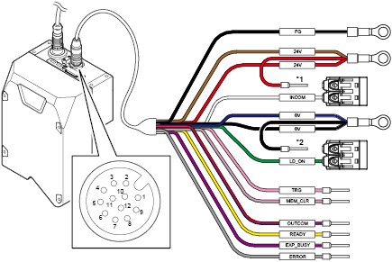
Overview of input/output signals
The following illustrates the I/O connector interface for head power supply.
|
No. |
Label |
Cable color |
Connection |
|
- |
FG |
Black |
- |
|
1 |
24V |
Brown |
24 VDC input |
|
9 |
24V |
Red |
24 VDC input |
|
3 |
INCOM |
White |
Common for input |
|
2 |
0V |
Blue |
24 VDC input (GND) |
|
7 |
0V |
Black |
24 VDC input (GND) |
|
4 |
LD_ON |
Green |
Laser ON input |
|
5 |
TRG |
Pink |
Trigger input |
|
11 |
MEM_CLR |
Pink/Gray |
Memory clear input |
|
12 |
OUTCOM |
Red/Blue |
Common for output |
|
6 |
READY |
Yellow |
Trigger input permission output |
|
10 |
EXP_BUSY |
Purple |
Capture-in-progress output |
|
8 |
ERROR |
Gray |
Error output (N.C.) |
*1 For the INCOM and LD_ON that have been short circuited via a connector, leave them short-circuited.
Signal input to the LJ-S Series head
Laser ON input
When this signal is input, the laser light is ready to be emitted.
Trigger input
This is the signal to start capturing.
Memory capacity clear input
Clears the memory of the area inside the head where the height and luminance images are kept.
Signal output from the LJ-S Series head
Trigger input permission output
When this signal is ON, a trigger input to start capturing can be accepted.
Capture-in-progress output
This signal outputs that an image is being captured.
Error output (N.C.)
Normal close (N.C.) output when the power is turned on or a system error occurs (ON when normal, OFF when an error occurs).
Trigger input
This is the signal to start capturing. Turning the TRG signal to ON starts capturing of the workpiece.
Note that the TRG signal can be accepted only when the READY signal is ON, which is the trigger input permission signal.
For details about the relationship between the TRG signal and the READY signal, see Chapter 7 in the LJ-S8000 Series (PC Connection) User’s Manual.
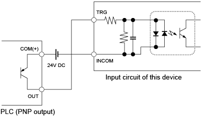
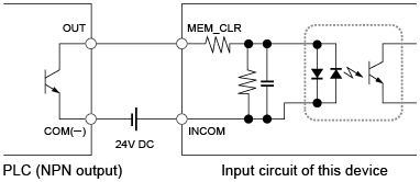
Wiring for the TRG signal
The following shows a wiring example for the TRG signal.
When the output instrument is compatible with the NPN open collector input
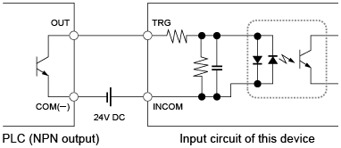
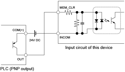
When the output instrument is compatible with the PNP open collector input
Wiring for the READY signal
The following shows a wiring example for the READY signal.
When trigger input is possible, this unit turns the READY signal to ON.
When the output instrument is compatible with the NPN open collector input
Connect an output from this unit to a PLC with a positive common
When the output instrument is compatible with the PNP open collector input
Connect an output from this unit to a PLC with a negative common
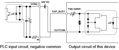
To determine the stop time of the workpiece, reference the EXP_BUSY signal. The EXP_BUSY signal is on when capturing is in progress, so do not move the workpiece when the signal is high.
(i.e. The duration of EXP_BUSY ON corresponds to the workpiece stop time.)
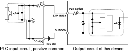
Wiring for the EXP_BUSY signal
The following shows a wiring example for the EXP_BUSY signal.
When the output instrument is compatible with the NPN open collector input
Connect an output from this unit to a PLC with a positive common
When the output instrument is compatible with the PNP open collector input
Connect an output from this unit to a PLC with a negative common